¶ Video Tutorials
- YouTube video guide: https://www.youtube.com/watch?v=c6iCg_Rsr0E
¶ 1. Pre-Installation: Tools and Preparation
Before handling hardware, ensure you have the following tools (not included in the package) and meet the environmental requirements:
¶ 1.1 Required Tools
- Electric Drill (8mm bit): Required for drilling holes for the wall expansion bolts if choosing vertical mounting.
- Level: To ensure the brackets and battery stack are perfectly horizontal.
- Insulating Gloves: Highly recommended for personal safety during cable handling.
¶ 1.2 Site Selection Standards
- Environment: Place the unit in a shaded area away from direct sunlight, rain and flammable materials.
- Ensure Wi-Fi signal strength: Make sure the Device is within the Wi-Fi coverage area.
- Clearance: The antenna casing on the device needs to be at least 15cm away from the wall.Maintain at least 5 cm of clearance around the top surface of the product, where the heat dissipation fins are located, to ensure proper ventilation, efficient heat dissipation, and reliable wireless communication.
- Distance: Ensure that the SolarFlow 2400 Pro is installed within the length range of the solar panel cables and the 3m AC connection cable.
- Surface: Use a solid, level floor to support the total weight of the main unit (27.8kg) and any expansion batteries.
To avoid wiring errors, identify the functional ports on the main unit: SolarFlow 2400 Pro Hardware Overview
¶ 2. Hardware Assembly Sequence
¶ 2.1 Battery Stacking
- Remove Covers: Peel off the silicone protective covers from the battery terminals on the main unit and the AB3000L battery modules.
- Align & Stack: Align the main unit's bottom terminal with the battery's top terminal and lower it carefully (Do not touch the metal pins of the ports with your hands or other objects).
- Confirm Connection: Press down firmly until you hear a clear "Click" sound, indicating the interfaces are fully locked.
- Capacity: You may stack up to 5 additional batteries for a maximum of 16.8kWh.
¶ 2.2 Mechanical Stabilization
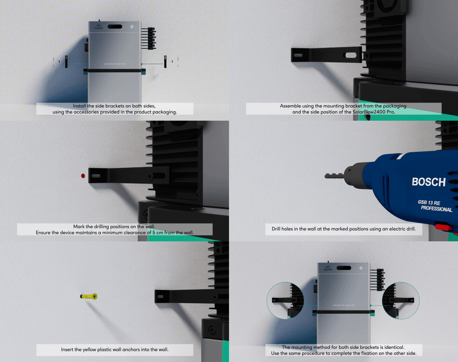
- Attach the side brackets to the SolarFlow 2400 Pro main unit using the M4 screws.
- Mark the drilling positions on the wall through the bracket slots.
- Drill and insert the expansion bolts to secure the system to the wall.
¶ 3. Electrical Integration
¶ 3.1 Solar Panel (DC) Connection
Before plugging in panels, look at the technical sticker on the back of your solar panel.
- Safety Check: Ensure the Open Circuit Voltage (Voc) is less than 55V. Values above 55V will damage the internal MPPT controller.
- Port Logic: One pair of positive (+) and negative (-) wires from a single panel (or parallel set) must go into the same PV port.
- Prohibited Action: Never connect the positive wire to one PV port and the negative wire to another (cross-paralleling), as this causes uneven power distribution and hardware failure.
.gif)
¶ 3.2 Grid (AC) Connection
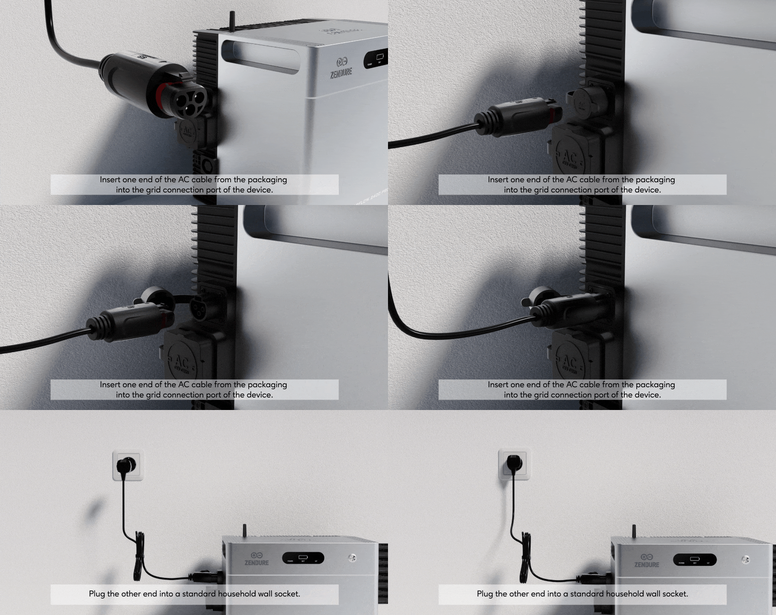
- Cable Setup: Plug the 3m 16A AC cable into the unit's upper AC port.
- Dedicated Socket: Plug the other end directly into a wall socket.
- Cable Management: Make sure the solar and AC cables can run straight down without significant bending.
- Avoid Power Strips: With the device installed on a dedicated circuit, it shall serve as the sole power source other than the utility.The dedicated circuit shall not be shared with any other sources or utilization equipment, except equipment connected downstream of the device.
[!Note]
The inverter is set to a default output power limit of 800W. If you need to exceed this limit, please have a licensed electrician visit your location to assess the safety of your circuit and ensure it complies with safety standards. After the electrician’s verification, you can apply to increase the power to 2400W via the Zendure App. Please see this page for detailed steps.
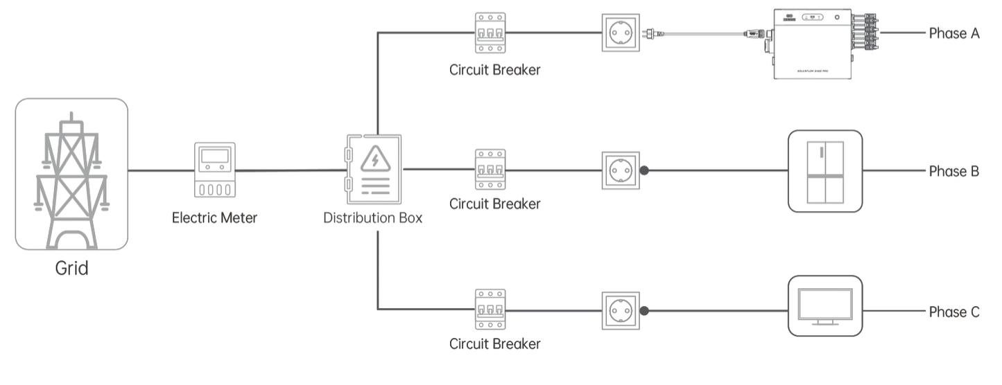
¶ 3.2.1 Single SolarFlow 2400 Pro Wiring Diagram
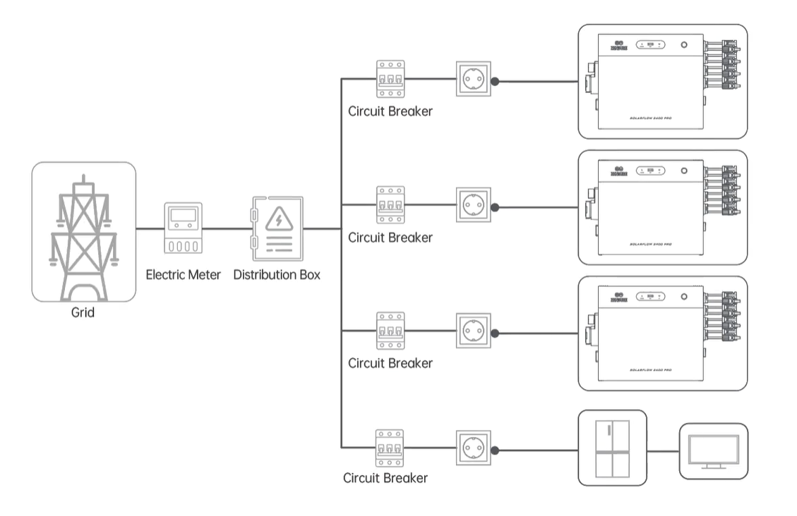
¶ 3.2.2 Multiple SolarFlow 2400 Pro Wiring Diagram
| Installation in single-phase electricity system | Installation in three-phase electricity system |
 |
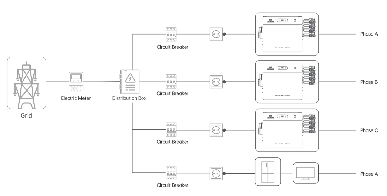 |
| Connect the inverter to a socket on the dedicated circuit, without any other appliances sharing the same circuit. Press and hold the button for 2 seconds to power on each inverter. | Connect each inverter to a socket on a dedicated circuit for each phase, ensuring no other appliances share the same circuit. Press and hold the button for 2 seconds to power on each inverter. |
- Each device’s peak power can reach 2400W. Connecting multiple devices to the same circuit can cause the circuit to overload, leading to potential safety risks.
- If your home does not have the required sockets and circuits, or if you lack the electrical knowledge to accurately identify whether these sockets or circuits meet the requirements, please request the assistance of an electrician. It is recommended to connect each devicer directly to a separate breaker. For detailed instructions, refer to this page.
- The total maximum output power of all devices is set to a default of 800W. If you need to exceed this limit, please invite an electrician to your home to ensure your wiring is safe and does not exceed the circuit load, or follow the installation guidelines in this page to connect each device directly to the breaker.
Next, you need to complete the device software connection on the app: SolarFlow 2400 Pro Software Setup Guide.