¶ Video Tutorials
- YouTube video guide: https://www.youtube.com/watch?v=X307oOWnYZI
¶ 1. Prerequisites and Safety
[!CAUTION]
Mandatory Professional Installation: This procedure involves handling high-voltage household wiring and must be performed by a certified electrician to prevent fire, electric shock, or death.
¶ 1.1 Required Components (Not Included)
- Insulating Gloves: Must be provided by the electrician.
- 16A Circuit Breaker: One unit is required for each SolarFlow 2400 AC+ main unit.
- Multimeter: For verifying the absence of voltage.
- Standard Electrical Tools: Screwdrivers, wire cutters, and wire strippers.
¶ 2. Installation Sequence
Step 1: Safety Preparation
- The electrician must wear insulating gloves before commencing work.
- Turn off the main household switch and the relevant branch circuit protection switches.
- Critical: Use a multimeter to verify that there is no voltage at the terminals before proceeding.
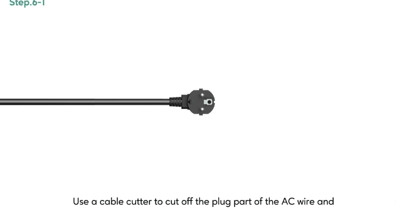
Step 2: AC Cable Modification
- Use a cable cutter to remove the standard plug from the provided 3m 16A AC Power Cable.
- Strip the outer insulation to expose the three internal wires: L (Live/Brown), N (Neutral/Blue), and PE (Ground/Yellow-Green).
- Strip the insulation from the tips of the three wires to expose the copper.
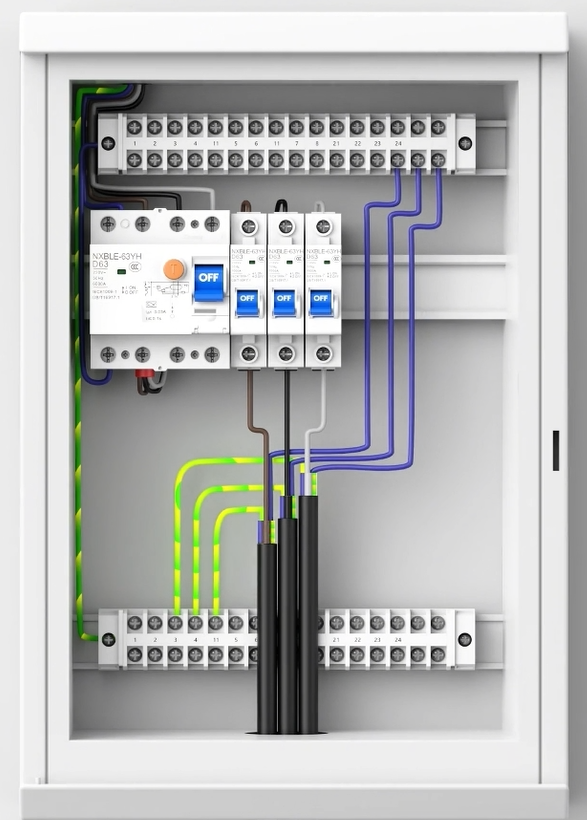
Step 3: Distribution Box Wiring
- Mount the Breaker: Install the new 16A circuit breaker onto the DIN rail inside the distribution box.
- Live (L) Connection: Connect the Brown (L) wire from the AC cable to the bottom of the new 16A circuit breaker.
- Neutral (N) Connection: Connect the Blue (N) wire to the neutral bar in the household panel.
- Ground (PE) Connection: Connect the Yellow-Green (PE) wire to the ground bar in the household panel.
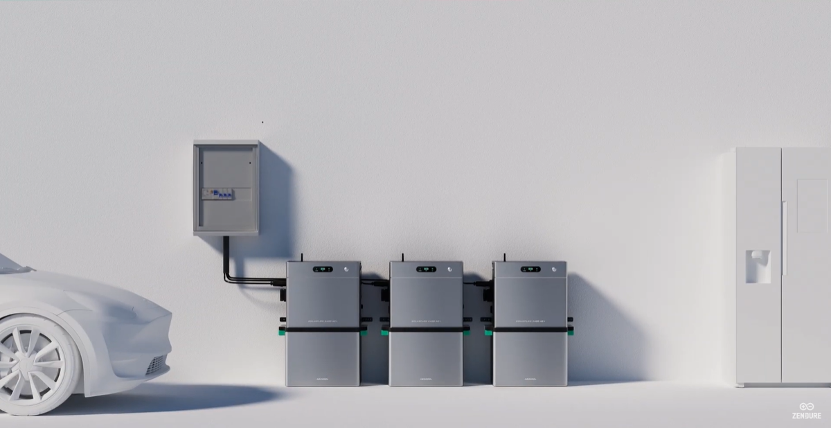
¶ Single-Phase Installation Diagram for SolarFlow 2400 AC+ (Single/Multiple Units)
| Wiring diagram the distribution box | Display | Please note | |
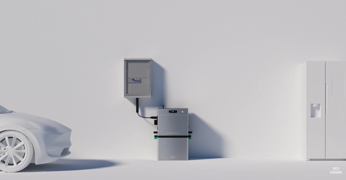
| Single Unit | 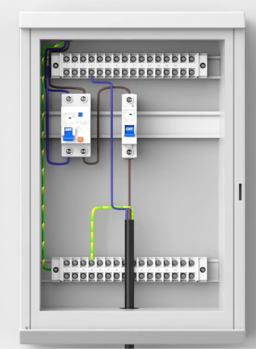 |
 |
1. Each SolarFlow 2400 AC+ unit has a rated power of 2400 W. 2. Check the main incoming capacity of the distribution box and calculate the total existing load. Then determine the remaining available capacity of the electrical system. Make sure the available capacity exceeds 2400 W to guarantee safe operation. |
| Multiple Units | 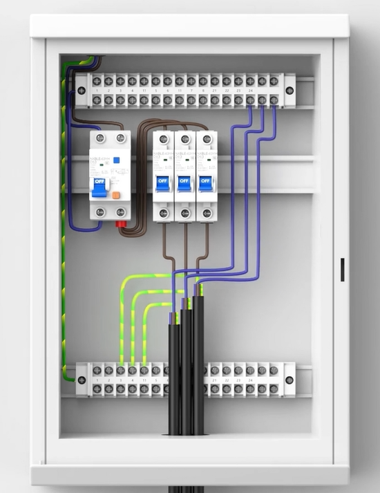 |
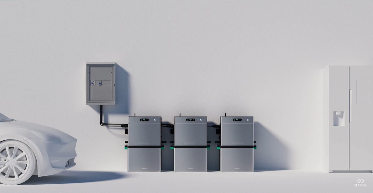 |
1. Each SolarFlow 2400 AC+ unit has a rated power of 2400 W. 2. Check the main incoming capacity of the distribution box and calculate the total existing load. Then determine the remaining available capacity of the electrical system. Make sure the available capacity exceeds 2400 W to guarantee safe operation. 3. Make sure the total available system capacity exceeds 2400W x N, N is the number of SolarFlow 2400 AC+ units to be installed. A safety redundancy should be reserved to ensure stable operation. |
¶ Three-Phase Installation Diagram for SolarFlow 2400 AC+ (Single/Multiple Units)
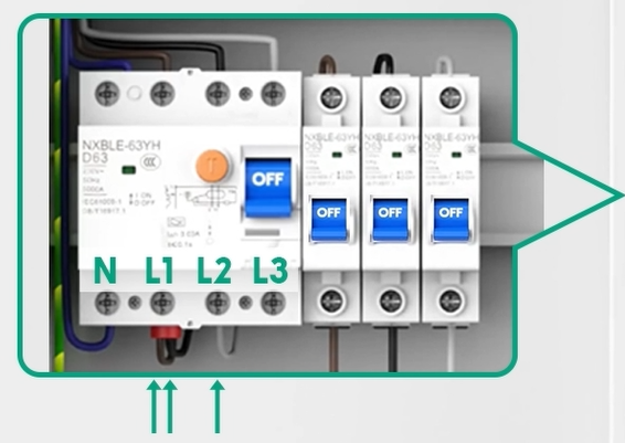
| Live (L) Connection Methods | Wiring diagram in the distribution box | Display | Please note | |
| Single Unit | / | 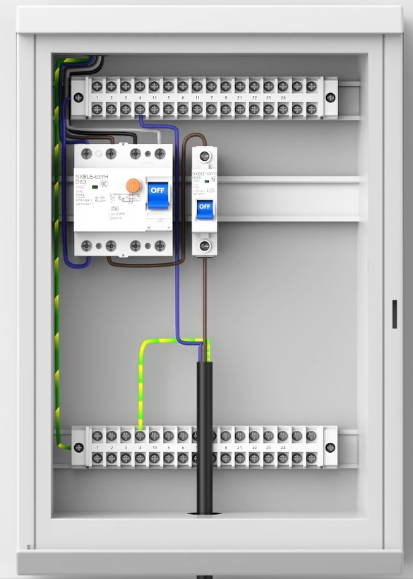 |
 |
1. Each SolarFlow 2400 AC+ unit has a rated power of 2400 W. 2. Check the main incoming capacity of the distribution panel and sum up the current load to determine the total available capacity. Make sure the available capacity exceeds 2400 W to guarantee safe operation. 3. Additionally, check the available capacity of each individual phase and install the SolarFlow 2400 AC+ on a phase where the available capacity exceeds 2400 W. |
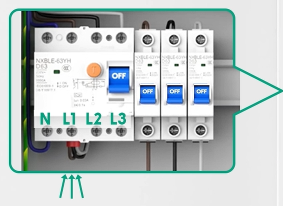
| Multiple Units | 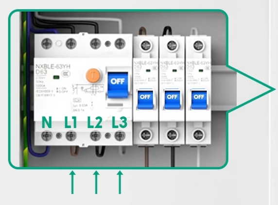 Metodo 1: Connect each circuit breaker to one of the three phases (L1, L2, and L3) from the main three-phase breaker, achieving a balanced distribution across all three phases. |
 |
 |
1. Each SolarFlow 2400 AC+ unit has a rated power of 2400W. 2. Check the main incoming capacity of the distribution box and sum up the existing loads to calculate the available system capacity. Make sure the total available system capacity exceeds 2400W x N (where N is the number of SolarFlow 2400 AC+ units to be installed). 3. Check the remaining available capacity on each phase and identify those which exceed 2400W. 4. Always install the SolarFlow 2400 AC+ on the phase with the highest available capacity to ensure safe and stable operation. |
 Metodo 2: This setup is suitable when phase L1 has ample capacity, L2 has moderate capacity, and L3 has little or no remaining capacity. |
||||
 Metodo 3: This method is suitable when only phase L1 has sufficient remaining capacity. |
Step 4: System Restoration
- Securely close and restore the distribution box panel.
- Turn on the main household switch and the new 16A circuit breaker.
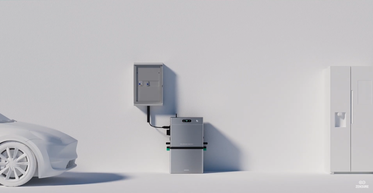
- Plug the specialized connector end of the AC cable into the AC Port of the SolarFlow 2400 AC+.
- Press and hold the button on the main unit for 2 seconds to power on.
¶ 3. Unlocking 2400W Output
By default, the system output is capped at 800W for standard socket safety. To enable the 2400W Premium mode:
- The electrician must verify that the wiring can safely handle the increased load.
- Open the Zendure App and navigate to Device Settings > On-grid Setting.
- Apply to increase the power limit.
- Sign the digital Safety Agreement within the app confirming professional installation.
Next Step: Once connected, you can configure your Base Load and Charging Settings to manage energy flow for high-power appliances like heat pumps.